Also known as HP PA12 Glass Beads, PA12 GB, Glass-filled PA12, PA12 GF, Nylon 12 GB

MJF Plastic PA12 Glass Beads- 3D Printing Material

HP Multi Jet Fusion [MJF]

Material info

About MJF Plastic PA12 Glass Beads- 3D Printing Material

PA 12 Glass Beads is a Multi Jet Fusion nylon plastic infused with glass beads that improve product stiffness and structural integrity. This material is 40% glass-filled which reduces warping during the printing process and over the product’s life. PA12 Glass Beads is great for flat and large parts that are prone to warping in Versatile Plastic and MJF PA12 Plastic and for functional parts that require high strength and dimensional accuracy.

Color & Finishes

Gray
Dark Gray

Technology

  • HP Multi Jet Fusion [MJF]

Technical Documents

Material Properties

Tensile modulus (ASTM D638)
2600 MPa (XY), 3000 MPa (Z)
Tensile strength (ASTM D638)
29 MPa (XY), 30 MPa (Z)
Elongation at break (ASTM D638)
10 %
Flexural modulus (23°C)(ASTM D790)
2400 MPa (XY), 2700 MPa (Z)

Description

Material Highlights
high stiffness, good dimensional stability, thin features and interlocking parts
Flammability degree (UL 94)
HB rating (<75mm/min for thickness of 0.75mm)
Electrical conductivity (UL 746A)
Dielectric strength value 3.38kV/mm to 7.29kV/mm (depending on orientation during printing), Volume Resistivity value 10^14 ohm-cm

Design Guidelines

Bounding Box

Bounding Box Max
284 x 380 x 380 mm
Note: Parts covering the exact maximum bounding box dimensions might not be printable due to printer limitations.

Bounding Box Min
4 x 4 x 1 mm or X + Y + Z > 9 mm

The bounding box is a 3D imaginary outline of a box that encloses the smallest area occupied by your model. Your model must be within the minimum and maximum bounding box sizes. If the size of the model is close to the maximum bounding box, then the printing orientation will be restricted.

Walls

Supported Wall Thickness Min
0.75 mm
Unsupported Wall Thickness Min
1.0 mm
A supported wall is connected at least on two sides of the wall, while an unsupported wall is connected only on one side of the wall. Walls that do not meet the minimum requirements may not survive printing and cleaning processes. Additionally, models may still be rejected based on the wall geometry of the model. Please consider the size of your model and reinforce the walls or add support structures as needed as minimum guidelines will not always be adequate for large models.

Wires

Supported Wires Min
1.0 mm
Unsupported Wires Min
1.0 mm
A wire is a circular, rectangular or even triangular feature that is thinner in its unconnected directions than its length. A supported wire is connected at least on two sides of the model, while an unsupported wire is connected on one side of the model. Wires that do not meet the minimum requirements may not survive printing and cleaning processes. Additionally, models may still be rejected based on the wire geometry of the model. Please consider the size of your model and reinforce the wires or add support structures as needed as minimum guidelines will not always be adequate for large models.

Details

Details Min Embossed
0.5 mm high & wide
Details Min Engraved
0.5 mm high & wide
For text, the ratio between width and depth, should be 1:1 and sans-serif fonts are preferred for line weight consistency.

Escape Holes

Single Escape Hole Diameter (Min)
4.0 mm
Multiple Escape Hole Diameter (Min)
2.0 mm
Escape holes are necessary to empty the support material of a hollow model. Two escape holes at the opposite ends of the model is optimal for the support removal process. Please consider the size of your model and make the escape holes bigger or add more escape holes as needed as minimum guidelines will not always be adequate for large models.
A single escape hole at the end of a cavity will not allow material in the corners near the escape hole to fully escape. So we recommend multiple escape holes at both ends of the cavity.

Clearance

Min
0.6 mm
Clearance is the space between two individual parts in a model. If the space among the individual parts do not meet the minimum clearance, then parts can fuse together or can be difficult to clean. This is important for movable pieces like hinges, gears, etc.

Sprues

2 mm thick, attached in at least 2 places per part

Sprues are wires that keep two or more parts together. Parts should be connected with a minimum of two sprues each. Please consider the size of your sprues and increase them as needed as minimum guidelines will not always be adequate for large models. If the sprues are within the guidelines and are broken, but there is no damage to your model, we will still ship them as is.

Interlocking & Enclosed Parts

Interlocking
Yes

Enclosed
Yes

Parts in File

Max
Up to 250

Accuracy

Accuracy ± 0.2 mm ± 0.5% of the length
For example: a product with dimensions of 50 x 50 x 100 mm can be 0.2 mm + 0.005*100 mm = 0.7 mm bigger or smaller in any direction.

Related Materials

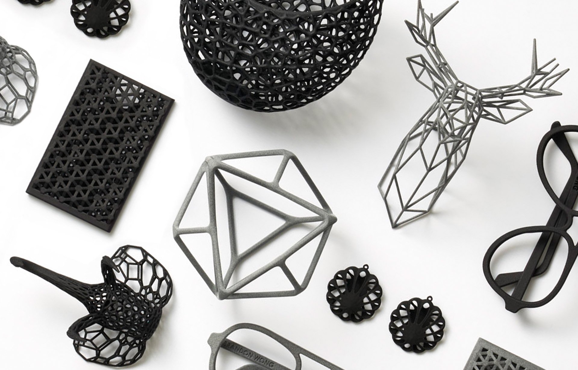
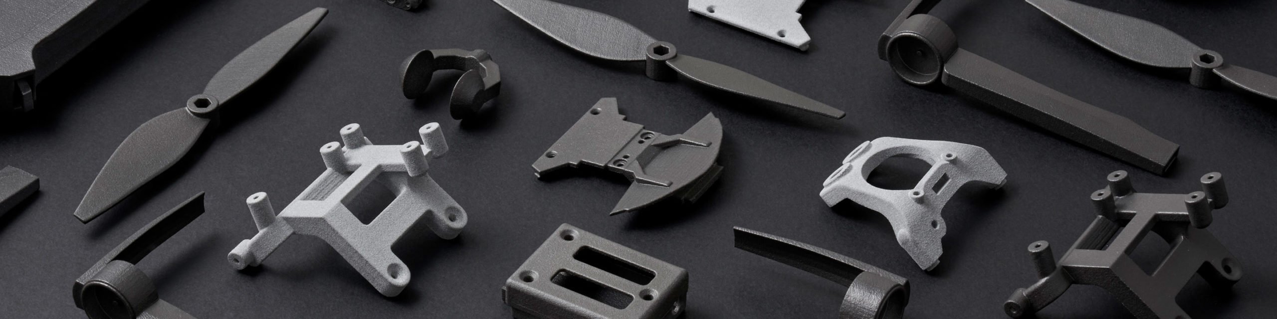
Also known as HP Multi Jet Fusion PA12, Professional Plastic, HP Nylon Plastic, PA12, Polyamide
MJF Plastic PA12 - 3D Printing Material
Application: Mechanical & structural parts, mounts, cases, eye frames, tech accessories, drone parts, home decor, miniatures, art, prosthetics
Learn More →
MJF, Polypropylene
Polypropylene (PP)- 3D Printing Material
Application: Wide range of automotive, consumer, industrial and medical applications
Learn More →

Stay up to date on promotions, case studies, and more.